Menu
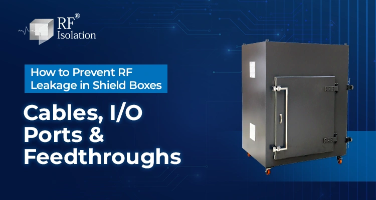
How to Prevent RF Leakage in Shield Boxes: Cables, I/O Ports & Feedthroughs
An RF shield box built with welded aluminum panels and a well-fitted door can still leak far more RF energy than its published isolation figure suggests. In most cases, the enclosure walls are not the problem.
The leakage happens at the points where something has to pass through the shield: a power cable, a USB lead, an antenna feed, or a data connector. Every cable, connector, and feedthrough is a potential aperture.
An unfiltered cable running through even a small opening can carry RF energy straight past a wall that would otherwise block it completely. This is why two shield boxes with identical construction can perform very differently once cables, I/O panels, and test instruments are connected.
This guide looks at how RF leakage actually occurs at cables, I/O ports, and feedthroughs, what filtered feedthroughs do to stop it, and how to select and maintain an I/O configuration that preserves the isolation your test setup depends on.
Key Takeways
- Cables Are Common Leakage Path: Unfiltered or improperly terminated cables can bypass an otherwise effective shield and significantly reduce enclosure isolation.
- Every Penetration Needs a Controlled RF Treatment: Connectors, feedthroughs and ventilation openings should be properly filtered, conductively bonded, sealed or designed using waveguide-below-cutoff principles according to their function.
- Filtered Feedthroughs Separate Signal From Noise: A filtered feedthrough lets power or data pass through the enclosure wall while attenuating RF energy that would otherwise ride along the same conductor.
- Connector Type Affects Leakage Risk: SMA and N-Type RF connectors, filtered USB and RJ-45 ports, and DB9/DB25 data connectors interact with shielding effectiveness differently and should be selected for the application.
- Cable Shield Termination Matters as Much as Filtering: A cable shield grounded through a pigtail lead instead of a 360-degree bond can reintroduce leakage even when a filter is present.
- Isolation Is Frequency-Dependent: A feedthrough or connector that performs well at lower frequencies may not maintain the same attenuation at the higher frequencies used by Wi-Fi 6E, 5G Sub-6 GHz, or Bluetooth.
- I/O Panels Should Be Planned Before Fabrication: Adding ports after the enclosure is built is more likely to compromise shielding than specifying the I/O layout at the design stage.
- Regular Inspection Prevents Gradual Leakage: Loose connectors, damaged filters, and worn cable glands degrade shielding effectiveness slowly, so periodic checks help catch leakage before it affects test results.
What Causes RF Leakage in a Shield Box?
RF leakage occurs whenever a conductive path or an opening allows RF energy to enter or exit the enclosure without being attenuated at the frequency of concern. In a properly built shield box, this happens far more often at cables, I/O connectors, and unfiltered feedthroughs than at the welded seams.
Two mechanisms are usually at work. The first is aperture leakage, where an opening in the shield wall, such as a connector cutout or ventilation slot, allows RF energy to pass directly through if it is not filtered, gasketed, or sized correctly relative to the wavelength involved.
The second is conducted leakage, where a cable or connector pin that penetrates the wall acts as a path for RF energy to travel along the conductor itself. An unfiltered cable can behave like an antenna, carrying signal energy through the shield boundary regardless of how well the surrounding panel is sealed.
Enclosures such as RF Isolation’s RF Standalone Shield Box address this with field-replaceable rear I/O modules, so connector types and filtering can be matched to the DUT without compromising the panel seal each time a port is added or changed.
Why Cables Are the Most Overlooked Leakage Path
A cable that enters a shield box carries two separate risks. The first is the signal or power it is meant to deliver. The second is any RF energy that couples onto the cable’s outer shield or conductors from inside or outside the enclosure.
If that cable passes through an unfiltered hole, or if its shield is grounded through a long lead instead of a direct connection to the panel, the cable itself becomes the leakage path. This happens even when the enclosure body, door, and gaskets are performing exactly as specified.
Cable entry hardware, not just cable quality, is what determines how much of this coupled energy actually crosses the shield boundary. A well-shielded cable brought through the wrong type of opening will still let RF energy ride along the outer shield surface into or out of the enclosure.
This is one of the reasons RF Isolation designs rear I/O panels around specific connector types rather than generic cutouts, so each cable entry point is filtered or bonded appropriately for the signal it carries.
How I/O Ports and Connectors Affect Shielding Effectiveness
Not every connector interacts with RF leakage the same way. RF connectors, data ports, and power feedthroughs each need a different filtering or bonding approach depending on the signal they carry and the frequency range involved.
The table below summarizes common I/O interface types and the RF leakage consideration associated with each.
| Interface | Purpose | RF Leakage Consideration |
|---|---|---|
| SMA / N-Type RF Connector | Antenna and RF signal feeds | Needs a bulkhead-mounted connector with continuous ground contact around the panel opening |
| USB 2.0 / 3.0 Filtered Port | Data and device connections | Requires common-mode filtering, since unfiltered USB cables can carry high-frequency noise along the data lines |
| RJ-45 Filtered Ethernet Port | Network and automated test-system connectivity | Filtered magnetics reduce conducted RF while preserving Ethernet signal integrity |
| DC Power Filtered Port | Powering the DUT or internal equipment | DC feedthrough filters attenuate RF riding on the power line without disrupting the DC supply |
| AC Power Filtered Port | Mains power entry | AC line filtering is needed wherever mains power crosses the shield boundary |
| DB9 / DB25 Filtered Data Port | Serial or multi-pin data and control connections | Each pin may need individual filtering depending on signal frequency and application |
| Fiber Feedthrough | Optical data links | Non-conductive fiber avoids most conducted leakage paths, but the housing still needs a sealed aperture |
| Ventilation / Filtered Airflow | Cooling for the DUT or internal equipment | Honeycomb or waveguide-below-cutoff vents allow airflow while strongly attenuating RF frequencies below the vent’s cutoff frequency. |
RF Isolation’s Rack Mount RF Shield Box offers rear I/O panels configured around this exact set of interface types, so the connector, filter, and cable entry can be matched to the DUT and test instrumentation before the enclosure is built.
Request Custom Configuration.
If your test setup needs a mix of RF, USB, Ethernet, and power connections crossing the shield wall, share your DUT's port count and frequency range with RF Isolation's engineering team for a suitable feedthrough configuration.
What Is a Filtered Feedthrough and Why It Matters
A filtered feedthrough allows power or data to cross the shield boundary while providing attenuation to unwanted RF energy on the conductors. Depending on the application, the filter may use capacitive, inductive, common-mode, or combined filtering elements.
When mounted correctly, with a continuous bond around the panel opening, the feedthrough shunts unwanted high-frequency energy to the enclosure wall before it can propagate further along the cable. The intended power or data signal passes through largely unaffected, provided the filter’s frequency rating is matched to the application.
Filtered DC Power Port
A filtered DC feedthrough allows power to reach the DUT or internal instrumentation while shunting RF noise on the conductor to the enclosure body, so the power line does not become an unintended leakage path.
Filtered RJ-45 Ethernet Port
A filtered Ethernet feedthrough preserves the data rate and signal integrity needed for automated test systems while reducing the RF energy that would otherwise be conducted along the network cable and its shield.
Cable Shielding, Grounding, and the Pigtail Effect
A shielded cable is only as effective as its termination. Where a cable’s outer shield is connected to the enclosure through a short length of wire, sometimes called a pigtail, that connection behaves like a small unintended antenna.
A pigtail termination adds inductance between the cable shield and enclosure. As frequency increases, the impedance of this connection rises, allowing a voltage to develop between the shield and enclosure and increasing common-mode coupling and radiation.
A 360-degree bond, made through a bulkhead connector or a properly fitted cable gland, maintains contact around the full circumference of the cable shield at the point where it crosses the enclosure wall. This is the more reliable approach for cables that need to carry RF-sensitive signals or that run near sensitive test frequencies.
Where cables must remain flexible and cannot use a hard bulkhead connector, ferrite chokes or common-mode filtering near the entry point can reduce, though not fully replace, the benefit of a solid 360-degree termination.
Other Leakage Points Worth Checking: Doors and Seams
Cables and I/O ports are the most frequent leakage paths, but they are not the only ones. Door contact fingers, gaskets, and panel seams can also allow RF energy to pass if contact pressure is lost or a seam is not fully continuous.
RF Isolation’s RF Shielded Door products use beryllium copper finger stock and a gasket system specifically to maintain shielding continuity around the access point, which is worth checking alongside the I/O panel if isolation drops unexpectedly.
How to Select the Right I/O Configuration for Your Test Setup
Selecting an I/O configuration starts with a clear picture of what needs to cross the shield wall, not just how many connectors are needed. The following factors typically shape the panel layout:
- The number and type of RF connections required, such as SMA or N-Type feeds for antennas or RF instrumentation.
- Whether the DUT or test system needs USB, Ethernet, or serial data connections for automation or logging.
- Power requirements, including whether AC mains, DC power, or both need to cross the enclosure wall.
- The highest frequency the enclosure needs to isolate, since filter and connector performance both vary with frequency.
- Whether the setup will run manually on a bench or needs to integrate into a rack-based or automated test system.
Enclosures such as RF Isolation’s RF Test Rack are built around this kind of planning, where I/O requirements, DUT quantity, and automation needs are worked out before the shielding structure is finalized rather than added afterward.
Request a Custom Quote
Planning the I/O panel before fabrication is easier than retrofitting ports later. RF Isolation's engineering team can review your connector list and frequency range during the design stage.
Diagnosing RF Leakage: A Troubleshooting Approach
When isolation measurements come back lower than expected, the I/O panel and cable entries are usually the first place to check before assuming a problem with the enclosure body.
| Symptom | Possible Cause | Recommended Check |
|---|---|---|
| Isolation lower than expected at all frequencies | Unfiltered or missing feedthrough filter | Inspect the I/O panel for unfiltered pass-throughs |
| Isolation degrades only at higher frequencies | Feedthrough filter with limited high-frequency attenuation | Verify the filter’s frequency rating against the test frequency |
| Intermittent leakage during testing | Loose or corroded connector, or a damaged gasket at the feedthrough | Check connector torque, gasket condition, and panel seating |
| Leakage appears after cable changes | Cable shield grounded with a pigtail instead of a 360-degree bond | Re-terminate the cable shield using a bulkhead connector or gland |
| Leakage increases gradually over time | Wear on filter components or connector contact degradation | Schedule periodic inspection of the I/O panel |
Best Practices Checklist to Prevent RF Leakage
- Specify filtered feedthroughs for every cable or connector that crosses the shield wall, matched to the signal type and frequency range.
- Terminate cable shields with a 360-degree bulkhead connection or gland rather than a pigtail lead wherever possible.
- Match each filter’s frequency rating to the DUT’s actual test frequency, rather than assuming a single filter type covers every application.
- Use honeycomb or waveguide-below-cutoff ventilation panels sized for the frequencies the enclosure needs to isolate.
- Avoid ad hoc cable pass-throughs or field-cut holes in the enclosure wall, since these are difficult to filter or bond correctly after the fact.
- Plan the I/O panel layout during the design stage, based on DUT connections, automation needs, and frequency range.
- Inspect connectors, gaskets, and filter components periodically, particularly after frequent door cycles or cable changes.
Why RF Isolation
Cable and I/O-related leakage is largely a design and configuration problem, which is why RF Isolation treats the rear I/O panel as part of the enclosure design rather than an accessory added afterward.
RF Isolation’s standalone and rack mount shield boxes use field-replaceable rear I/O modules configured around SMA, N-Type, RJ-45 filtered Ethernet, DC and AC power filtered ports, USB filtered ports, DB9/DB25 filtered data connections, and fiber feedthrough options, so the panel can be matched to the DUT and test instrumentation rather than forced into a fixed layout.
Every enclosure is manufactured at RF Isolation’s ISO 9001:2015 certified facility in Ahmedabad, India, and tested for shielding effectiveness before dispatch. This applies to the assembled unit, including its I/O panel and cable entries, not just the enclosure body in isolation.
RF Isolation’s engineering team also reviews DUT dimensions, connector requirements, and frequency range before a quote is issued through the Services consultation process, which is where most cable and feedthrough-related leakage risks can be identified and designed out before the enclosure is built.
Conclusion
An RF shield box is only as effective as its weakest leakage path, and that path is usually a cable, connector, or feedthrough rather than the enclosure wall or door. Filtering, correct cable shield termination, and I/O panel planning are what keep the measured isolation close to the rated specification.
Get in Touch to discuss your test requirements
Whether you are specifying a new enclosure or diagnosing leakage in one you already own, RF Isolation can review your cable, connector, and feedthrough setup and recommend the right configuration.
Frequently Asked Questions
Cables and I/O connectors are the most common leakage paths, more often than the enclosure walls or door. An unfiltered cable, an improperly grounded shield, or a missing feedthrough filter can all let RF energy bypass an otherwise well-shielded enclosure.
A properly specified feedthrough filter is selected to pass the intended power or data signal while attenuating unwanted RF energy on the same conductor. The filter’s frequency rating should be matched to the DUT’s operating frequency so the desired signal is not affected.
A pigtail lead used to ground a cable shield behaves like a short antenna and can reradiate RF energy at higher frequencies, reducing effective isolation. A 360-degree bond at a bulkhead connector or gland maintains continuous contact around the full circumference of the cable shield.
Retrofitting ports after fabrication is possible but more likely to affect shielding effectiveness than planning the I/O panel layout in advance. RF Isolation’s field-replaceable rear I/O modules are designed to allow reconfiguration without extensive rework.
Connectors, gaskets, and filter components should be checked periodically, particularly after frequent door cycles or cable changes, since gradual wear can reduce shielding effectiveness without an obvious cause. Loose connectors and damaged gaskets are common early indicators.
Ventilation openings can reduce shielding effectiveness if they are not properly designed. Honeycomb vents use waveguide-below-cutoff principles to attenuate RF below their cutoff frequency while still allowing airflow.