Menu
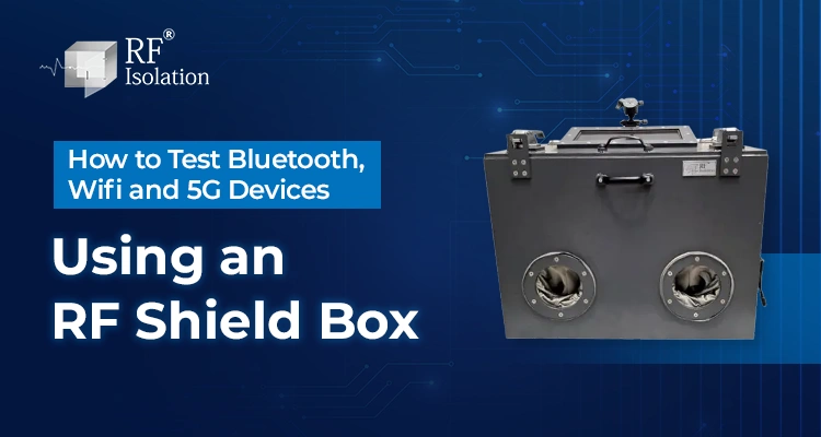
How to Test Bluetooth, Wifi and 5G Devices Using an RF Shield Box
A wireless device can appear unstable even when the device itself is working correctly. Nearby access points, Bluetooth peripherals, cellular signals and adjacent test stations can change the RF environment between one test run and the next.
An RF shield box helps by placing the device under test, or DUT, inside a conductive enclosure that attenuates unwanted external signals and limits unintended radiation from leaving the test space. The goal is not “zero RF.” It is a controlled environment in which the intended test signal dominates the measurement.
For Bluetooth, Wi-Fi and 5G testing, the core workflow is similar: define the measurement, identify the operating frequencies, verify isolation at those frequencies, configure filtered interfaces, fix DUT and antenna positions, establish a baseline, then run the protocol-specific test sequence.
Key Takeways
- Start With the Measurement: Define whether you are testing pairing, throughput, sensitivity, coexistence, regression performance or production pass/fail behavior.
- Verify Isolation by Frequency: Shielding effectiveness is frequency-dependent, so one dB figure cannot describe performance across every band.
- Control Cable Paths: Power, USB, Ethernet and RF connections can become leakage paths unless the feedthrough is designed for the test.
- Fix DUT Geometry: Keep orientation, antenna spacing and cable routing consistent between runs.
- Separate Shielding and Absorption: Shielding controls RF entering or leaving the enclosure; absorber reduces reflections inside it.
- Use Protocol-Specific Tests: Bluetooth, Wi-Fi and 5G need different instruments and measurements even when the same enclosure concept is used.
- Treat 5G Coverage Carefully: Sub-6 GHz and millimeter-wave testing can require very different enclosure, connector and filter performance.
- Match the Form Factor to Workflow: Desktop boxes suit bench testing, while rack mount boxes and test racks support structured or automated systems.
What Does an RF Shield Box Do During Wireless Device Testing?
An RF shield box creates a bounded RF environment around the DUT. Its conductive body, door contacts, seams and filtered interfaces reduce unwanted coupling between the DUT and the surrounding laboratory or production floor.
This improves repeatability because the test system, rather than nearby wireless traffic, controls the signal path. The enclosure does not replace a radio tester, signal generator, network emulator, access point, or spectrum analyzer. It provides a controlled environment in which those tools operate.
RF Isolation’s current RF Desktop Shield Box range is positioned for bench-level WLAN, Wi-Fi, Bluetooth, 4G and 5G testing, with configurable I/O and multiple enclosure formats.
How Do You Set Up an RF Shield Box for Testing?
1. Define the Test Objective
Decide exactly what the test must determine. Typical objectives include connection behavior, receiver sensitivity, throughput, transmit behavior, coexistence, regression testing, and production pass/fail validation.
2. Identify Every Operating Frequency
List every radio that may be active in the DUT. Bluetooth operates in the 2.4 GHz ISM band from 2400 to 2483.5 MHz. For Wi-Fi and 5G, verify the exact bands enabled on the DUT and test instrument instead of relying only on the protocol name.
3. Verify Isolation at Those Frequencies
Do not select an enclosure from its highest advertised isolation number alone. Check shielding-effectiveness data at the frequencies used by the test. Door contacts, seams, ventilation and I/O interfaces can become the limiting paths.
4. Configure Filtered Power, Data and RF Interfaces
The DUT may need DC or AC power, Ethernet, USB, control lines or conducted RF connections. These interfaces should pass the required service without creating an uncontrolled RF path through the enclosure.
5. Fix the DUT and Antenna Position
Use a repeatable DUT location or fixture. Keep antenna spacing, orientation and cable routing consistent. In a compact enclosure, geometry can affect the internal RF field, so movement between runs can create measurement differences.
6. Establish a Baseline
Establish a controlled baseline using a known RF source and receiver or spectrum analyzer at the relevant test frequencies. Keep antenna positions and test geometry fixed, then compare the reference condition with the closed-box condition. Also check for unexpected coupling through cables, feedthroughs, seams or interfaces. An open-versus-closed ambient RF comparison can be used as a quick functional check, but it should not replace frequency-specific shielding verification.
7. Run and Repeat the Test
Execute the required sequence, log the same metrics and repeat under the same setup. If results vary, change one factor at a time so the source of variation can be isolated.
How Do You Test Bluetooth Devices in an RF Shield Box?
Bluetooth testing commonly focuses on pairing, reconnection, receiver performance, advertising behavior, data transfer, or audio behavior.
A practical sequence is to place the DUT and test antenna or companion device at fixed positions, connect filtered power and control interfaces, close the enclosure, establish the intended Bluetooth link, record the target metrics, then repeat the sequence with controlled attenuation or changed test conditions.
Useful measurements may include connection success, RSSI, reconnection behavior, sensitivity, data behavior, and audio performance. The shield box supports the controlled test environment, but it does not itself perform Bluetooth qualification or certification.
RF Isolation has a dedicated Bluetooth Device Testing solution for Bluetooth Classic, BLE, R&D, pre-compliance and production-oriented environments.
How Do You Test Wi-Fi Devices in an RF Shield Box?
For Wi-Fi testing, the objective is to prevent surrounding WLAN traffic from influencing the DUT while the intended access point, traffic generator or RF instrument controls the connection.
Common measurements include association and reconnection behavior, RSSI, receiver sensitivity, throughput, packet behavior, antenna comparisons, and Wi-Fi/Bluetooth coexistence.
Keep the DUT, test antenna, and internal cable geometry fixed. For conducted testing, account for cable and feedthrough losses. For radiated testing, repeat the same antenna position and use an absorber when internal reflections are affecting repeatability. Absorber manages reflections; it does not replace the shielding function of the conductive enclosure.
How Do You Test 5G Devices in an RF Shield Box?
The first step is to identify the actual NR band and frequency range used by the DUT. A generic “5G-ready” label is not enough for shield-box selection.
3GPP maintains separate RF requirement families for NR Frequency Range 1 and Frequency Range 2. RF Isolation’s own product information also demonstrates why frequency-specific evaluation matters, with isolation performance specified against particular frequencies rather than as one universal number.
For a Sub-6 GHz 5G module, router or CPE, connect the DUT to the intended network simulator or RF test system, route the required filtered interfaces, verify the closed-box baseline, establish the network connection, then run sensitivity, throughput, regression or production tests under controlled signal conditions.
Do not assume a Sub-6 GHz enclosure can support FR2 or mmWave tests. The complete enclosure system, including feedthroughs and filters, needs appropriate characterization at a higher frequency.
RF Isolation lists dedicated 5G Device Testing solutions, but selection should still be based on the individual DUT frequency, size, isolation requirement and I/O configuration.
Testing 5G Sub-6 GHz or a higher-frequency application? Share the exact band, DUT dimensions, test method, and required interfaces so the enclosure can be evaluated without assuming universal 5G coverage. Talk to a Shielding Specialist.
Bluetooth vs Wi-Fi vs 5G Shield Box Testing
| Test Area | Bluetooth | Wi-Fi | 5G |
|---|---|---|---|
| Primary RF Concern | Crowded 2.4 GHz environment | Nearby WLAN traffic and coexistence | Frequency-dependent isolation across the NR band |
| Common Test Goals | Pairing, BLE behavior, sensitivity | Throughput, RSSI, sensitivity | Connection, sensitivity, throughput, validation |
| Typical Equipment | Bluetooth tester, companion device, attenuator | Access point, traffic generator, RF tester | Network simulator, call box, RF instrument |
| Key Enclosure Check | Isolation around 2.4 GHz | Coverage for all DUT Wi-Fi bands | Verified isolation at the exact 5G frequency |
| Common Setup Risk | Nearby Bluetooth devices | Uncontrolled access points | Assuming Sub-6 GHz performance applies to mmWave |
What RF Shield Box Mistakes Cause Unreliable Results?
Using an isolation number without a frequency: Always match the shielding specification to the DUT bands.
Running cables through door gaps: A cable can compromise shielding continuity. Use appropriate filtered interfaces or RF feedthroughs.
Moving the DUT between runs: Orientation, antenna position, and cable geometry can change radiated results.
Confusing absorber with shielding: Absorber reduces internal reflections; it does not replace the conductive RF barrier.
Ignoring the door interface: Contamination, wear or misalignment at RF contacts can reduce repeatability over time.
Choosing the wrong form factor: A bench setup and an automated production station have different requirements for access, I/O and rack integration.
Which RF Shield Box Type Fits Your Test Workflow?
| Enclosure Type | Best Fit | Main Selection Question |
|---|---|---|
| Desktop RF Shield Box | Bench R&D and small DUTs | Does the DUT fit with antennas, fixtures and cables? |
| Standalone Shield Box | Larger DUTs and flexible lab setups | Is more internal space or free-standing use required? |
| Rack Mount RF Shield Box | Structured racks and automation | Is 19-inch rack integration and organized rear I/O needed? |
| RF Test Rack | Production and multi-instrument systems | Do throughput, automation and multiple stations drive the design? |
RF Isolation’s Rack Mount RF Shield Box is designed for rack-based wireless testing, while its RF Test Rack is positioned for larger production and R&D environments.
Moving from lab validation to repeatable production testing? RF Isolation can align the enclosure format, rear I/O, DUT access, and rack layout with the test process. Request Custom Configuration.
What Information Should You Provide for Shield Box Selection?
Prepare the DUT dimensions, all operating frequencies, required isolation or measurement margin, antenna arrangement, power needs, USB/Ethernet/RF interfaces, mounting format, number of DUTs and automation requirements. If radiated reflections are a concern, also define the absorber requirement and internal antenna geometry.
These inputs allow the enclosure to be specified around the test instead of forcing the test to work around the enclosure.
Why Consider RF Isolation for This Application?
RF Isolation designs and manufactures RF shielding equipment in Ahmedabad, India, including desktop, standalone and rack mount shield boxes, RF test racks and RF chambers. Current product pages describe customization around DUT size, I/O interfaces, absorber options and rack integration.
For Bluetooth, Wi-Fi and 5G projects, this application-specific configuration matters because frequency coverage, DUT geometry, feedthroughs, antenna placement, cables and automation requirements all affect the final test setup.
Conclusion
Testing Bluetooth, Wi-Fi and 5G devices inside an RF shield box requires more than placing the DUT in a metal enclosure. Reliable results depend on a defined test objective, verified isolation at the operating frequency, controlled I/O, repeatable DUT positioning, and a protocol-specific test sequence.
Bluetooth testing often emphasizes pairing, reconnection, and sensitivity. Wi-Fi testing commonly focuses on throughput, RSSI, sensitivity, and coexistence. 5G testing requires additional care because the enclosure must match the actual NR frequency range, especially when moving beyond Sub-6 GHz.
When those factors are controlled, an RF shield box provides a practical foundation for repeatable R&D, validation, pre-compliance, and production testing.
Frequently Asked Questions
Yes, if the enclosure provides adequate shielding effectiveness across every required frequency and has suitable space and interfaces. Do not assume multi-protocol suitability from one isolation value.
There is no universal dB value. The requirement depends on ambient signal strength, DUT receiver sensitivity, intended test level, measurement margin, frequency, and interface leakage.
RF absorber is useful when internal reflections or standing waves affect a radiated setup. It is not a replacement for RF shielding and should be selected for the measurement method and frequency range.
Yes. Conductive paths through the enclosure can become leakage paths if they are not properly filtered. The interface must support the required data function while preserving suitable RF attenuation.
Only when the complete enclosure system is characterized for the required FR2 or mmWave frequency. Seams, contacts, connectors and filters that work at lower frequencies may not provide the same isolation at shorter wavelengths.
Use rack mount when the enclosure needs to integrate into a structured test rack, automated test system or production station. A desktop box is usually more practical for workbench R&D and lower-volume validation.